Why Optimise the Hydraulic Tank?
Over recent years, environmental concerns have led to pollution reduction legislation and a growth in the electrification of mobile machinery. At the same time, rising cost pressures are driving OEMs to seek design solutions that maximise performance and minimise total cost of ownership. Focusing on hydraulic tank optimisation can offer many benefits to help solve these challenges:
- Reduce hydraulic tank size
- Optimise fluid dearation
- Improve temperature dissipation
- Optimise filtration performance
Watch an interview with our tank optimisation experts to learn more


Smaller Footprint
A footprint reduction of up to 75 L per machine frees up space for battery installation enabling electrification technologies.

Lower Emissions
A reduction in the weight of the hydraulic reservoir by up to 100 kg decreases fuel consumption and carbon dioxide emissions.
Decreased Costs
A smaller tank reduces steel and hydraulic oil demand decreasing manufactring costs by up to €1,000,000 per machine series per year.

Reduced Environmental Impact
A smaller hydraulic tank requires less oil so disposal can be reduced by up to 500,000 L per machine series per year.
R&D Capabilities Video
Take a sneak peek at Parker's R&D facilities. Learn how we work with you to improve the design of the hydraulic reservoir from computer simulations to laboratory and on-site testing.

Tank Optimisation Programme
We work with you from concept to design to speed up your development time

Consultation
STEP 1
Parker’s engineers have decades of experience in hydraulic filtration and tank optimisation. We work closely with your engineering team, from concept to final design, to create a total system solution. This approach reduces your development time and brings your innovations to market faster.
Our team of experts will work with you to identify key objectives, whether it be tank size reduction, removal of air, heat dissipation or improvement of flow streamlines. We study your system, analyse your CAD models to identify locations of filters and any baffle plates, any suctions and flow rates involved.
Simulation
STEP 2
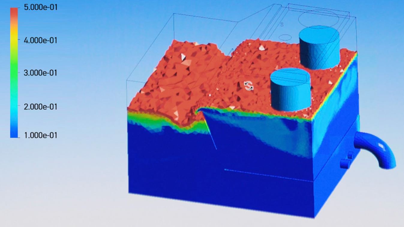
After an initial consultation to understand your system, Parker will use computation fluid dynamics (CFD) to simulate the current performance of your hydraulic reservoir. CFD can determine oil flow streamlines, oil and air phase fractions in the tank, heat distribution and oil properties. The effectiveness of the internal components and flow path to the suction line(s) are then investigated to identify:
- Location and type of return filter, including a standard or customised funnel
- Positioning, shape and size of internal baffle plate(s)
- Positioning of suction points
- Location of the air breather, fluid level gauge and other components

Laboratory Testing
STEP 3
After the completion of the simulations a physical tank will be tested at our hydraulic filtration site in Urjala, Finland, to confirm that the performance of the reservoir matches the simulation results.
By using the Oilpas test unit we can determine air in oil contamination by measuring the quantity of and size of air bubbles. Besides the air in oil testing we also visually observe the behaviour of the air bubbles.
After the physical tank testing the reservoir design can be finalised for series production.

On-Site Testing
STEP 4
The final step of the tank optimisation program will be on-site testing to test the performance of the hydraulic tank on the equipment. By installing the Oilpass test unit we can measure the quantity of and size of air bubbles during real operating conditions.
Other tests can be done simultaneously to get a better understanding about performance of the full hydraulic system.
- Differential pressure testing
- Cleanliness level testing
- Aeration testing

Success Stories
Sandvik Mining and Rock Technology
Sankvik Mining and Rock Technology contacted Parker to help them with their hydraulic tank design. Their goals were to optimise serviceability, reduce footprint to accommodate the battery and improve tank deaeration.
Optimisation process: The process included simulation, lab testing and on-site testing on the machine to measure the ability of the tank to deaerate the incoming oil.
Customised solution: The solution included a customised tank and filtration products positioned to optimise service ease and safety. The integrated Parker filters guarantee the quality of the filtration in the tank which improves the service life of the machine. Tank footprint was reduced, creating extra battery space but also reducing tank oil volume lessening environmental impact.

Volvo Construction Equipment
Parker’s team of hydraulic experts worked with Volvo Construction Equipment when developing their new F series excavator. When designing their new model, they wanted to increase the cab size to improve the operator experience. They also wanted to develop an optimised hydraulic tank that was suitable for all of their models from the F series platform. This would allow them to standardise the assembly and minimise the number of parts in production, effectively reducing their tooling costs.
Parker worked closely with Volvo to develop an integrated solution, designed to minimise the hydraulic tank volume.
Selecting the correct top tank filter: The iProtect® GLF Filter Series was chosen as it provides in-to-out filtration to allow a safer and cleaner filter element replacement. The iProtect® GLF Filter Series also provides more filtration media surface, reducing flow velocity and oil foaming via the diffuser.
Hydraulic reservoir performance simulation: Parker used computational fluid dynamics (CFD) to ensure space inside the tank was optimised. David Lazzaro, Lead Engineer Hydraulic, Volvo Construction Equipment commented that “it helped a lot during development as it allowed us to find the correct positioning of the diffuser and check tank deaeration without doing physical tests”. This allowed for time and money savings for tooling.
Verifying the solution: David found that “the help of Parker with the Oilpas tool was also very useful to verify all of the different assumptions taken during the CFD analysis”.

Useful Resources
Video
Parker hydraulic tank optimisation expert interview
Learn about the market trends driving hdyraulic tank optimisation and how Parker can work with you from concept to design to bring your innovations to market.
Video
Parker's tank optimisation R&D facility overview
Learn how we work with you to improve the design of the hydraulic reservoir from computer simulations to laboratory and on-site testing.
White paper
Design innovation through high-fidelity simulations
Learn how parker use computer simulations to help you innovate your hydraulic tank design.
Brochure
Hydraulic tank optimisation brochure
The hydarulic tank optimisation brochure is now available to download
Case Study
Hydraulic reservoir optimisation
Discover how Parker used CFD to establish an optimised hydraulic tank design when challenged with improving deaeration while reducing tank size.
Video
Sandvik Mining and Rock Technology
Find out how Parker helped worked with a customer to optimise servicing, reduce hydraulic tank footprint and improve deaeration on their machines.
Featured Products

iProtect® GLF Series
Tank top return line hydraulic oil filter


FMU & LPS Series
Filter pressure and vacuum indicator

AB Series
Top-mounted breathers and filler breathers

Tank Accessories
Fluid level / temperatures gauges, float and capacitive level switches

SE Series
Suction elements / inbuilt filters