
CHALLENGE:
IMPROVE DEAERATION WHILE REDUCING TANK SIZE
Improving hydraulic tank deaeration increases machine controllability and prevents system corrosion. A reduction in tank size was required to increase battery installation capacity.
SOLUTION:
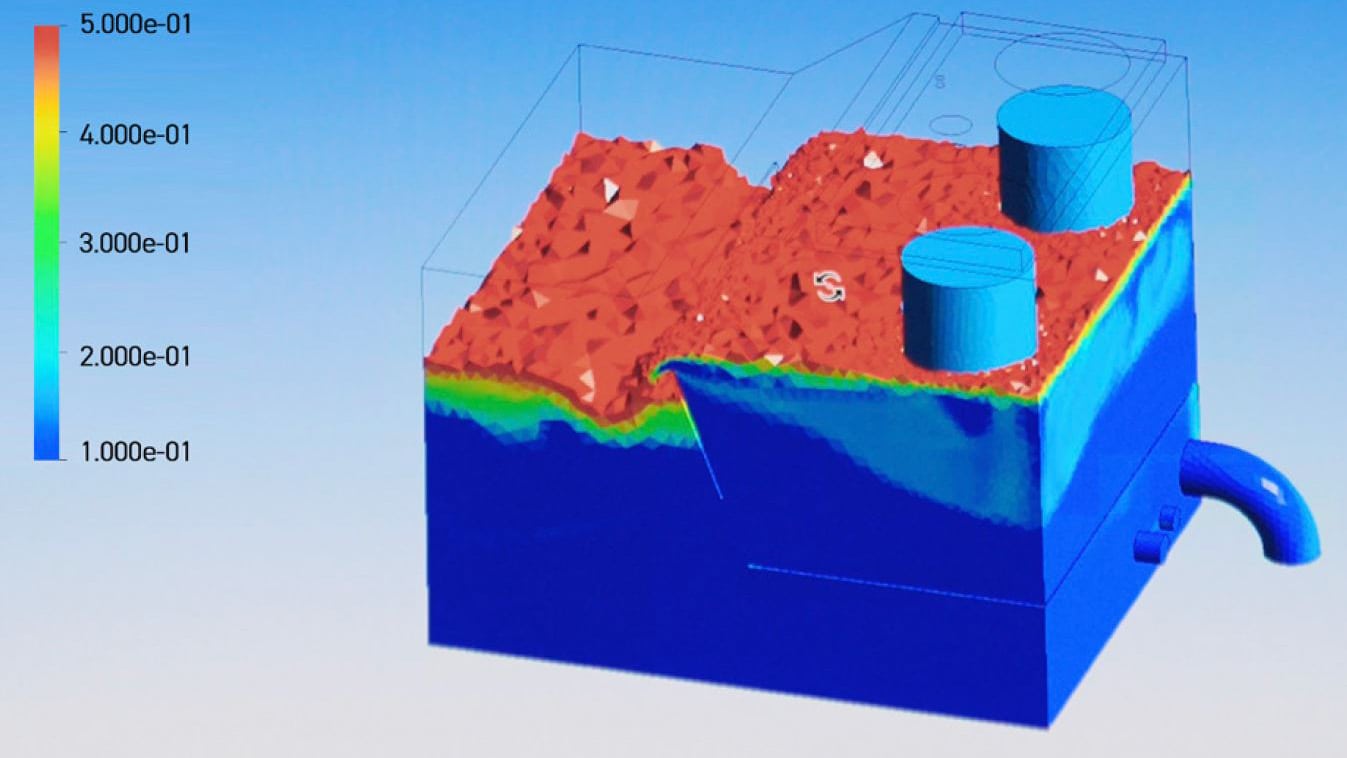
USING CFD TO ESTABLISH OPTIMISED TANK DESIGN
Using computation fluid dynamics (CFD), Parker evaluated the outer geometry, internal structure and components to establish the best possible tank design.
BENEFITS:
CFD IMPROVED ALL IMPORTANT ASPECTS OF THE TANK
By implementing the future tank design determined from CFD, tank footprint was reduced by 71 L, increasing battery installation capacity and air contamination was decreased by 76%.
Saving space and improving efficiency
Parker’s tank optimisation programme focuses on hydraulic reservoir design to save space, improve machine controllability and reduce total cost of ownership. With trends towards electrification of vehicles, corporate reduction of environmental impact and cost reduction, tank optimisation provides several benefits:
• Reduction in air contamination
• Improved heat dissipation and flow streamlines
• Increased battery installation capacity • Reduction in fuel consumption and emissions
• Improved machine efficiency
• Decreased oil consumption and disposal
• Reduction in manufacturing, maintenance and repair costs
Read the full story here.
Parker's Tank Optimisation Programme

Consultation
STEP 1
Parker’s engineers have decades of experience in hydraulic filtration and tank optimisation. We work closely with your engineering team, from concept to final design, to create a total system solution. This approach reduces your development time and brings your innovations to market faster.
Our team of experts will work with you to identify key objectives, whether it be tank size reduction, removal of air, heat dissipation or improvement of flow streamlines. We study your system, analyse your CAD models to identify locations of filters and any baffle plates, any suctions and flow rates involved.
Simulation
STEP 2
After an initial consultation to understand your system, Parker will use computation fluid dynamics (CFD) to simulate the current performance of your hydraulic reservoir. CFD can determine oil flow streamlines, oil and air phase fractions in the tank, heat distribution and oil properties. The effectiveness of the internal components and flow path to the suction line(s) are then investigated to identify:
- Location and type of return filter, including a standard or customised funnel
- Positioning, shape and size of internal baffle plate(s)
- Positioning of suction points
- Location of the air breather, fluid level gauge and other components

Laboratory Testing
STEP 3
After the completion of the simulations a physical tank will be tested at our hydraulic filtration site in Urjala, Finland, to confirm that the performance of the reservoir matches the simulation results.
By using the Oilpas test unit we can determine air in oil contamination by measuring the quantity of and size of air bubbles. Besides the air in oil testing we also visually observe the behaviour of the air bubbles.
After the physical tank testing the reservoir design can be finalised for series production.

On-Site Testing
STEP 4
The final step of the tank optimisation program will be on-site testing to test the performance of the hydraulic tank on the equipment. By installing the Oilpass test unit we can measure the quantity of and size of air bubbles during real operating conditions.
Other tests can be done simultaneously to get a better understanding about performance of the full hydraulic system.
- Differential pressure testing
- Cleanliness level testing
- Aeration testing